NCERT Solutions for Current Electricity Class 12 Physics
Book Solutions1
Answer
Emf of the battery, E = 12 V
Internal resistance of the battery, r = 0.4 Ω
Maximum current drawn from the battery = I
According to Ohm’s law,

The maximum current drawn from the given battery is 30 A.
2
Answer
Emf of the battery, E = 10 V
Internal resistance of the battery, r = 3 Ω
Current in the circuit, I = 0.5 A
Resistance of the resistor = R
The relation for current using Ohm’s law is,

R = 20 - 3 = 17 Ω
Terminal voltage of the resistor = V
According to Ohm’s law,
V = IR
= 0.5 × 17
= 8.5 V
Therefore, the resistance of the resistor is 17 Ω and the terminal voltage is
8.5 V.
3
(a) Three resistors 1 Ω, 2 Ω, and 3 Ω are combined in series. What is the total resistance of the combination?
(b) If the combination is connected to a battery of emf 12 V and negligible internal resistance, obtain the potential drop across each resistor.
Answer
(a) Three resistors of resistances 1 Ω, 2 Ω, and 3 Ω are combined in series. Total resistance of the combination is given by the algebraic sum of individual resistances.
Total resistance = 1 + 2 + 3 = 6 Ω
(b) Current flowing through the circuit = I
Emf of the battery, E = 12 V
Total resistance of the circuit, R = 6 Ω
The relation for current using Ohm’s law is,

Potential drop across 1 Ω resistor = V1
From Ohm’s law, the value of V1 can be obtained as
V1 = 2 × 1= 2 V … (i)
Potential drop across 2 Ω resistor = V2
Again, from Ohm’s law, the value of V2 can be obtained as
V2 = 2 × 2= 4 V … (ii)
Potential drop across 3 Ω resistor = V3
Again, from Ohm’s law, the value of V3 can be obtained as
V3 = 2 × 3= 6 V … (iii)
Therefore, the potential drop across 1 Ω, 2 Ω, and 3 Ω resistors are 2 V, 4 V, and 6 V respectively.
4
(a) Three resistors 2 Ω, 4 Ω and 5 Ω are combined in parallel. What is the total resistance of the combination?
(b) If the combination is connected to a battery of emf 20 V and negligible internal resistance, determine the current through each resistor, and the total current drawn from the battery.
Answer
(a) There are three resistors of resistances,
R1 = 2 Ω, R2 = 4 Ω, and R3 = 5 Ω
They are connected in parallel. Hence, total resistance (R) of the combination is given by,

(b) Emf of the battery, V = 20 V
Current (I1) flowing through resistor R1 is given by,
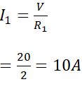
Current (I2) flowing through resistor R2 is given by,
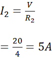
Current (I3) flowing through resistor R3 is given by,

Total current, I = I1 + I2 + I3 = 10 + 5 + 4 = 19 A
Therefore, the current through each resister is 10 A, 5 A, and 4 A respectively and the total current is 19 A.
5

Answer
Room temperature, T = 27°C
Resistance of the heating element at T, R = 100 Ω
Let T1 is the increased temperature of the filament.
Resistance of the heating element at T1, R1 = 117 Ω
Temperature co-efficient of the material of the filament

T1=
Therefore, at 1027°C, the resistance of the element is 117Ω.
6
Answer
Length of the wire, l =15 m
Area of cross-section of the wire, a = 6.0 × 10⁻⁷ m2
Resistance of the material of the wire, R = 5.0 Ω
Resistivity of the material of the wire = ρ
Resistance is related with the resistivity as

Therefore, the resistivity of the material is 2 × 10⁻⁷ Ω m.
7
Answer
Temperature, T1 = 27.5°C
Resistance of the silver wire at T1, R1 = 2.1 Ω
Temperature, T2 = 100°C
Resistance of the silver wire at T2, R2 = 2.7 Ω
Temperature coefficient of silver = α
It is related with temperature and resistance as

Therefore, the temperature coefficient of silver is 0.0039°C−1.
8
Answer
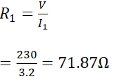
Supply voltage, V = 230 V
Initial current drawn, I1 = 3.2 A
Initial resistance = R1, which is given by the relation,
Steady state value of the current, I2 = 2.8 A
Resistance at the steady state = R2, which is given as
![]()
Temperature co-efficient of nichrome, α = 1.70 × 10⁻⁴ °C −1
Initial temperature of nichrome, T1= 27.0°C
Study state temperature reached by nichrome = T2
T2 can be obtained by the relation for α,

Therefore, the steady temperature of the heating element is 867.5°C.
9

Answer
Current flowing through various branches of the circuit is represented in the given figure.

I1 = Current flowing through the outer circuit
I2 = Current flowing through branch AB
I3 = Current flowing through branch AD
I2 − I4 = Current flowing through branch BC
I3 + I4 = Current flowing through branch CD
I4 = Current flowing through branch BD
For the closed circuit ABDA, potential is zero i.e.,
10I2 + 5I4 − 5I3 = 0
2I2 + I4 −I3 = 0
I3 = 2I2 + I4 … (1)
For the closed circuit BCDB, potential is zero i.e.,
5(I2 − I4) − 10(I3 + I4) − 5I4 = 0
5I2 + 5I4 − 10I3 − 10I4 − 5I4 = 0
5I2 − 10I3 − 20I4 = 0
I2 = 2I3 + 4I4 … (2)
For the closed circuit ABCFEA, potential is zero i.e.,
−10 + 10 (I1) + 10(I2) + 5(I2 − I4) = 0
10 = 15I2 + 10I1 − 5I4
3I2 + 2I1 − I4 = 2 … (3)
From equations (1) and (2), we obtain
I3 = 2(2I3 + 4I4) + I4
I3 = 4I3 + 8I4 + I4
− 3I3 = 9I4
− 3I4 = + I3 … (4)
Putting equation (4) in equation (1), we obtain
I3 = 2I2 + I4
− 4I4 = 2I2
I2 = − 2I4 … (5)
It is evident from the given figure that,
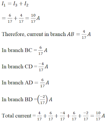
I1 = I3 + I2 … (6)
Putting equation (6) in equation (1), we obtain
3I2 +2(I3 + I2) − I4 = 2
5I2 + 2I3 − I4 = 2 … (7)
Putting equations (4) and (5) in equation (7), we obtain
5(−2 I4) + 2(− 3 I4) − I4 = 2
− 10I4 − 6I4 − I4 = 2
17I4 = − 2

10
(a) In a metre bridge [Fig. 3.27], the balance point is found to be at 39.5 cm from the end A, when the resistor Y is of 12.5 Ω. Determine the resistance of X. Why are the connections between resistors in a Wheatstone or meter bridge made of thick copper strips?
(b) Determine the balance point of the bridge above if X and Y are interchanged.
(c) What happens if the galvanometer and cell are interchanged at the balance point of the bridge? Would the galvanometer show any current?
Answer
A metre bridge with resistors X and Y is represented in the given figure.

(a) Balance point from end A, l1 = 39.5 cm
Resistance of the resistor Y = 12.5 Ω
Condition for the balance is given as,

= 8.2 Ω
Therefore, the resistance of resistor X is 8.2 Ω.
The connection between resistors in a Wheatstone or metre bridge is made of thick copper strips to minimize the resistance, which is not taken into consideration in the bridge formula.
(b) If X and Y are interchanged, then l1 and 100−l1 get interchanged.
The balance point of the bridge will be 100−l1 from A.
100−l1 = 100 − 39.5 = 60.5 cm
Therefore, the balance point is 60.5 cm from A.
(c) When the galvanometer and cell are interchanged at the balance point of the bridge, the galvanometer will show no deflection. Hence, no current would flow through the galvanometer.
11
A storage battery of emf 8.0 V and internal resistance 0.5 Ω is being charged by a 120 V dc supply using a series resistor of 15.5 Ω. What is the terminal voltage of the battery during charging? What is the purpose of having a series resistor in the charging circuit?
Answer
Emf of the storage battery, E = 8.0 V
Internal resistance of the battery, r = 0.5 Ω
DC supply voltage, V = 120 V
Resistance of the resistor, R = 15.5 Ω
Effective voltage in the circuit = V1
R is connected to the storage battery in series. Hence, it can be written as
V1 = V − E
V1 = 120 − 8 = 112 V
Current flowing in the circuit = I, which is given by the relation,

Voltage across resistor R given by the product, IR = 7 × 15.5 = 108.5 V
DC supply voltage = Terminal voltage of battery + Voltage drop across R
Terminal voltage of battery = 120 − 108.5 = 11.5 V
A series resistor in a charging circuit limits the current drawn from the external source. The current will be extremely high in its absence. This is very dangerous.
12
Answer
Emf of the cell, E1 = 1.25 V
Balance point of the potentiometer, l1= 35 cm
The cell is replaced by another cell of emf E2.
New balance point of the potentiometer, l2 = 63 cm

Therefore, emf of the second cell is 2.25V.
13
The number density of free electrons in a copper conductor estimated in Example 3.1 is 8.5 × 1028 m−3. How long does an electron take to drift from one end of a wire 3.0 m long to its other end? The area of cross-section of the wire is 2.0 × 10⁻⁶ m2 and it is carrying a current of 3.0 A.
Answer
Number density of free electrons in a copper conductor, n = 8.5 × 1028 m−3 Length of the copper wire, l = 3.0 m
Area of cross-section of the wire, A = 2.0 × 10⁻⁶ m2
Current carried by the wire, I = 3.0 A, which is given by the relation,
I = nAeVd
Where,
e = Electric charge = 1.6 × 10⁻¹⁹ C


= 2.7 × 10⁴
Therefore, the time taken by an electron to drift from one end of the wire to the other is 2.7 × 10⁴ s.
14
Answer
Surface charge density of the earth, σ = 10−9 C m−2
Current over the entire globe, I = 1800 A
Radius of the earth, r = 6.37 × 10⁶ m
Surface area of the earth,
A = 4πr2
= 4π × (6.37 × 106)2
= 5.09 × 10¹⁴ m2
Charge on the earth surface,
q = σ × A
= 10−9 × 5.09 × 1014
= 5.09 × 10⁵ C
Time taken to neutralize the earth’s surface = t

Therefore, the time taken to neutralize the earth’s surface is 282.77 s.
15
(a) Six lead-acid type of secondary cells each of emf 2.0 V and internal resistance 0.015 Ω are joined in series to provide a supply to a resistance of 8.5 Ω. What are the current drawn from the supply and its terminal voltage?
(b) A secondary cell after long use has an emf of 1.9 V and a large internal resistance of 380 Ω. What maximum current can be drawn from the cell? Could the cell drive the starting motor of a car?
Answer
(a) Number of secondary cells, n = 6
Emf of each secondary cell, E = 2.0 V
Internal resistance of each cell, r = 0.015 Ω
series resistor is connected to the combination of cells.
Resistance of the resistor, R = 8.5 Ω
Current drawn from the supply = I, which is given by the relation,

Terminal voltage, V = IR = 1.39 × 8.5 = 11.87 A
Therefore, the current drawn from the supply is 1.39 A and terminal voltage is
11.87 A.
(b) After a long use, emf of the secondary cell, E = 1.9 V
Internal resistance of the cell, r = 380 Ω
Hence, maximum current

Therefore, the maximum current drawn from the cell is 0.005 A. Since a large current is required to start the motor of a car, the cell cannot be used to start a motor.
16
Answer
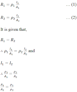
Resistivity of aluminium, ρAl = 2.63 × 10⁻⁸ Ω m
Relative density of aluminium, d1 = 2.7
Let l1 be the length of aluminium wire and m1 be its mass.
Resistance of the aluminium wire = R1
Area of cross-section of the aluminium wire = A1
Resistivity of copper, ρCu = 1.72 × 10⁻⁸ Ω m
Relative density of copper, d2 = 8.9
Let l2 be the length of copper wire and m2 be its mass.
Resistance of the copper wire = R2
Area of cross-section of the copper wire = A2
The two relations can be written as

Mass of the aluminium wire,
m1 = Volume × Density
= A1l1 × d1 = A1 l1d1 … (3)
Mass of the copper wire,
m2 = Volume × Density
= A2l2 × d2 = A2 l2d2 … (4)
Dividing equation (3) by equation (4), we obtain

It can be inferred from this ratio that m1 is less than m2. Hence, aluminium is lighter than copper.
Since aluminium is lighter, it is preferred for overhead power cables over copper.
17
Current A | Voltage V | Current A | Voltage V |
0.2 | 3.94 | 3.0 | 59.2 |
0.4 | 7.87 | 4.0 | 78.8 |
0.6 | 11.8 | 5.0 | 98.6 |
0.8 | 15.7 | 6.0 | 118.5 |
1.0 | 19.7 | 7.0 | 138.2 |
2.0 | 39.4 | 8.0 | 158.0 |
Answer
It can be inferred from the given table that the ratio of voltage with current is a constant, which is equal to 19.7. Hence, manganin is an ohmic conductor i.e., the alloy obeys Ohm’s law. According to Ohm’s law, the ratio of voltage with current is the resistance of the conductor. Hence, the resistance of manganin is 19.7 Ω.19
Choose the correct alternative:
(a) Alloys of metals usually have (greater/less) resistivity than that of their constituent metals.
(b) Alloys usually have much (lower/higher) temperature coefficients of resistance than pure metals.
(c) The resistivity of the alloy manganin is nearly independent of/increases rapidly with increase of temperature.
(d) The resistivity of a typical insulator (e.g., amber) is greater than that of a metal by a factor of the order of (1022/103).
Answer
(a) Alloys of metals usually have greater resistivity than that of their constituent metals.
(b) Alloys usually have lower temperature coefficients of resistance than pure metals.
(c) The resistivity of the alloy, manganin, is nearly independent of increase of temperature.
(d) The resistivity of a typical insulator is greater than that of a metal by a factor of the order of 1022.
20
(a) Given n resistors each of resistance R, how will you combine them to get the (i) maximum (ii) minimum effective resistance? What is the ratio of the maximum to minimum resistance?
(b) Given the resistances of 1 Ω, 2 Ω, 3 Ω, how will be combine them to get an equivalent resistance of (i) (11/3) Ω (ii) (11/5) Ω, (iii) 6 Ω, (iv) (6/11) Ω?
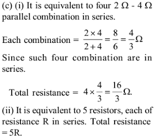
(c) Determine the equivalent resistance of networks shown in Fig. 3.31.
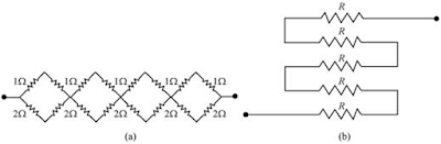
Answer


21

Answer
The resistance of each resistor connected in the given circuit, R = 1 Ω
Equivalent resistance of the given circuit = R’
The network is infinite. Hence, equivalent resistance is given by the relation,

Negative value of R’ cannot be accepted. Hence, equivalent resistance,

22
Figure 3.33 shows a potentiometer with a cell of 2.0 V and internal resistance 0.40 Ω maintaining a potential drop across the resistor wire AB. A standard cell which maintains a constant emf of 1.02 V (for very moderate currents up to a few mA) gives a balance point at 67.3 cm length of the wire. To ensure very low currents drawn from the standard cell, a very high resistance of 600 kΩ is put in series with it, which is shorted close to the balance point. The standard cell is then replaced by a cell of unknown emf ε and the balance point found similarly, turns out to be at 82.3 cm length of the wire.

(a) What is the value ε?
(b) What purpose does the high resistance of 600 kΩ have?
(c) Is the balance point affected by this high resistance?
(d) Is the balance point affected by the internal resistance of the driver cell?
(e) Would the method work in the above situation if the driver cell of the potentiometer had an emf of 1.0 V instead of 2.0 V?
(f ) Would the circuit work well for determining an extremely small emf, say of the order of a few mV (such as the typical emf of a thermo-couple)? If not, how will you modify the circuit?
Answer
(a) Constant emf of the given standard cell, E1 = 1.02 V
Balance point on the wire, l1 = 67.3 cm
A cell of unknown emf (ε) replaced the standard cell. Therefore, new balance point on the wire, l = 82.3 cm
The relation connecting emf and balance point is,

The value of unknown emf is 1.247 V.
(b) The purpose of using the high resistance of 600 kΩ is to reduce the current through the galvanometer when the movable contact is far from the balance point.
(c) The balance point is not affected by the presence of high resistance.
(d) The point is not affected by the internal resistance of the driver cell.
(e) The method would not work if the driver cell of the potentiometer had an emf of 1.0 V instead of 2.0 V. This is because if the emf of the driver cell of the potentiometer is less than the emf of the other cell, then there would be no balance point on the wire.
(f) The circuit would not work well for determining an extremely small emf. As the circuit would be unstable, the balance point would be close to end A. Hence, there would be a large percentage of error.
The given circuit can be modified if a series resistance is connected with the wire AB. The potential drop across AB is slightly greater than the emf measured. The percentage error would be small.
23

Answer
Resistance of the standard resistor, R = 10.0 Ω
Balance point for this resistance, l1 = 58.3 cm
Current in the potentiometer wire = i
Hence, potential drop across R, E1 = iR
Resistance of the unknown resistor = X
Balance point for this resistor, l2 = 68.5 cm
Hence, potential drop across X, E2 = iX
The relation connecting emf and balance point is,

= 11.75 Ω
Therefore, the value of the unknown resistance, X, is 11.75 Ω.
If we fail to find a balance point with the given cell of emf, ε, then the potential drop across R and X must be reduced by putting a resistance in series with it. Only if the potential drop across R or X is smaller than the potential drop across the potentiometer wire AB, a balance point is obtained.
24
Figure 3.35 shows a 2.0 V potentiometer used for the determination of internal resistance of a 1.5 V cell. The balance point of the cell in open circuit is 76.3 cm. When a resistor of 9.5 Ω is used in the external circuit of the cell, the balance point shifts to 64.8 cm length of the potentiometer wire. Determine the internal resistance of the cell.

Answer
Internal resistance of the cell = r
Balance point of the cell in open circuit, l1 = 76.3 cm
An external resistance (R) is connected to the circuit with R = 9.5 Ω
New balance point of the circuit, l2 = 64.8 cm
Current flowing through the circuit = I
The relation connecting resistance and emf is,

Therefore, the internal resistance of the cell is 1.68Ω.